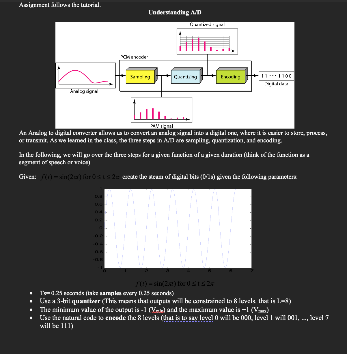
Analog To Digital Converter Circuit Diagram In digital circuits the voltage signal is in two forms, either as a logic high or logic low logic levels, which represent binary values of 1 or 0. In a analog to digital converters (ADC), the input analog signal is represented as a digital magnitude, while a digital-analog converter (DAC) converts the digital magnitude back to an analog signal. Analog Signal - An analog signal is any continuous signal for which the time varying feature of the signal is a representation of some other time varying quantity i.e., analogous to another time varying signal. The following techniques can be used for Digital to Analog Conversion: 1. Amplitude Shift keying -

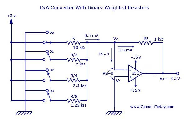
What is DAC (Digital to Analog Converter)? Digital to analog converter is an electronic circuit that converts any digital signal (such as binary signal) into an analog signal (voltage or current). The digital signal such as the binary signal exist in the form of bits & it is the combination of 1's & 0's (or High & low voltage levels).

PDF 'Understanding Data Converters' Circuit Diagram
One way to analyze and understand how this circuit works is to replace the R/2R ladder with its Thévenin equivalent circuit, then treat it as an inverting amplifier. Digital to Analog Converter Performance Specs. Several factors affect the performance of a DAC. Here are a few of the major ones to watch out for. A Digital to Analog Converter (DAC or D-to-A)is a device that converts digital codes to an analog signal. There are many categories of DACs. Some of these categories include sigma-deltaDACs, pulse width modulators, interpolating and high speed DACs. In this paper the focus will be on the interpolating and high speed DACs.

Digital-to-analog (DAC) converter circuits are an important component in many of today's technologies, converting digital signals into analog signals. A DAC circuit diagram is a graphical representation of how these components are connected in order to create an effective DAC system.

Digital To Analog Converter Circuit Diagram
The DtoA models a digital-to-analog converter with several types of distortion. The input to the model is a digital word in integer form, while the output is a quantized real baseband signal. At every execution of this model, 1 sample is read from the input and RepeatOutput samples are written to the output. We just need a way to provide the required integer input. This technical overview

The process of conversion of a digital input signal (1s and 0s) into an analog output signal is called digital to analog conversion (D/A). The digital signal usually encoded using a binary code consisting of 0s and 1s. In electronics, the circuits and systems which help in converting the binary code into analog signals are called digital to
