Based Smart Water Management Systems for Residential Buildings in Circuit Diagram Then create a new template. I have named it the "Water Level Monitoring System". Now, click the datastreams tab and create two virtual pins. Please enter the height of your water tank to the maximum value of the V0 pin. Virtual Pin > Name - Water Level / PIN - V0 / MIN - 0 / MAX - 16 (Height of the water tank) Well, I have already written several articles on the water level monitoring system. But today's IoT-based water level monitoring system is different from those projects, because many things have changed in the last few months. For example, Blynk V1.0, which was also known as Blynk Legacy, has now been replaced by the Blynk V2.0.
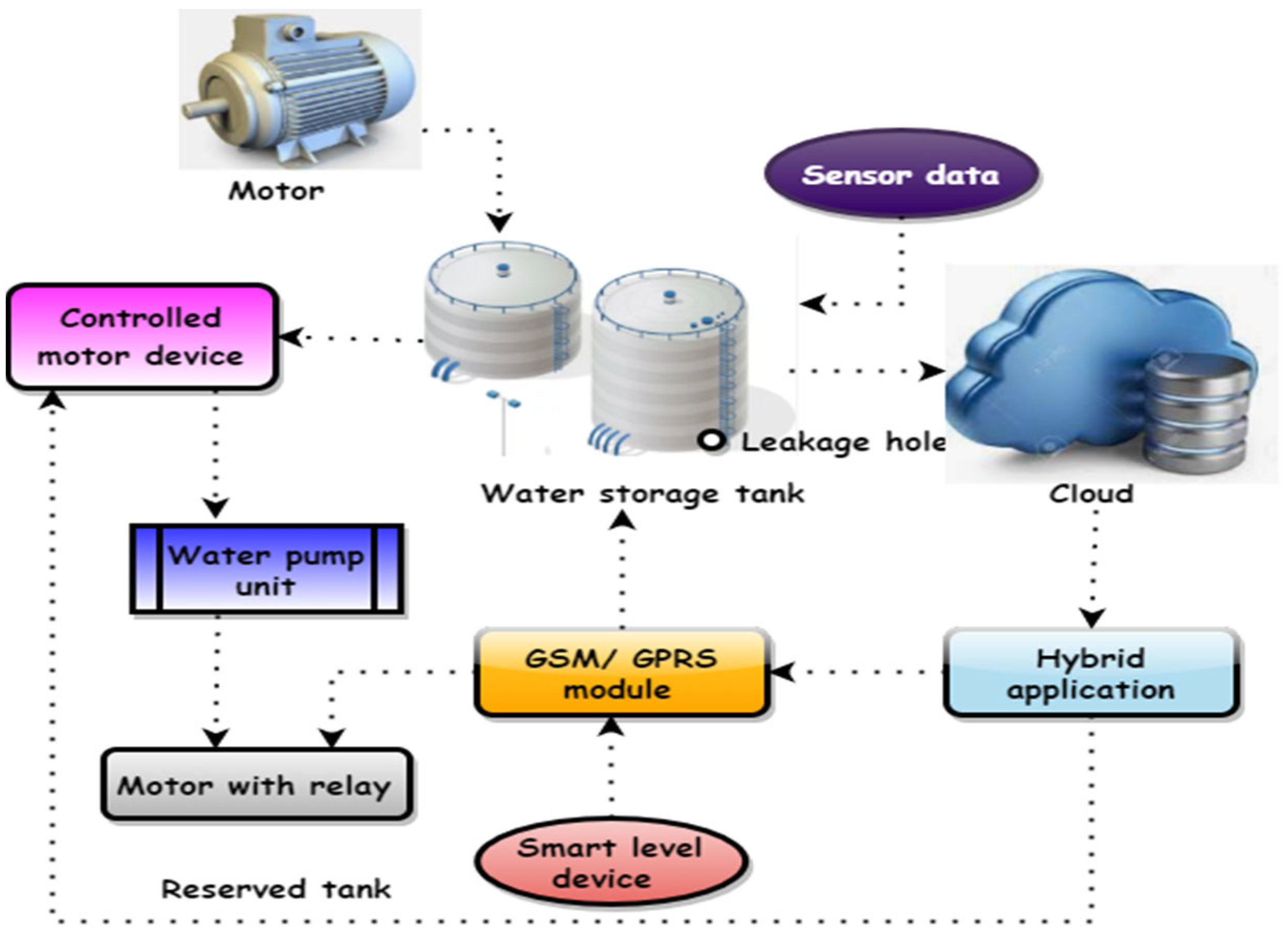
Our ESP32 Water Level Monitoring System with Blynk provides real-time monitoring of water levels in tanks, reservoirs, and irrigation systems. It utilizes the ESP32 microcontroller and Blynk IoT platform to offer visualizations, alerts, and remote monitoring, enabling efficient water resource management and preventing overflow or depletion. This project aims to automate the process of water level monitoring of water tank and water pump control using an ESP32 microcontroller, a waterproof ultrasonic sensor, a relay module, and the Blynk IoT app. In multi-story buildings or residential complexes with shared water tanks, this system can automate the filling process and provide It is intended to be immersed in a water tank and its capacitance varies with the level of the water. A city-scale water distribution network's 4 m water storage tank has been used to assess the sensor's performance. Gama-Moreno et al. [5] proposed The InteRface for Monitoring Water Tanks (IRMA) as a system that would

PDF Internet of Things (IoT) based Smart Water Tank Level Monitoring and ... Circuit Diagram
In this project we are taking a cylindrical water tank. The formula to calculate the volume of the tank is Volume = π x r² x h. Where. π = 3.14. r = Radius of the tank (Base of tank) you can find the diameter and divide it by 2 to get the radius in cm. h = Height of the tank in cm. The value of "r" will be static once you get it.

While the recent version of the water level monitoring system is based on the Nodemcu esp8266 wifi module to monitor the water level on my cell phone and also control the water pump from anywhere around the world, So the IoT version of the Water level monitoring system entirely depends on this tutorial. So I highly recommend you should read It will be a contactless water level measurement system. First, we will learn to interface HC-SR04 with ESP32. After that, we will see program our ESP32 board with the ultrasonic sensor to build our water monitor web server. The web server will show the current water level measured as the distance in cm by HC-SR04. So let's begin!
DIY Water Level Monitoring System Circuit Diagram
While climate change, pollution monitoring, and industrial water usage are broad reasons for monitoring water levels, more specific applications are discussed throughout this page. The level is perceived as one of the most straightforward water parameters. In general, it is the level of water in a body of water, in groundwater, in a tank, etc.

Overview. In this project, we will build an IoT Based Water Level Control & Monitoring System with ESP8266 and Waterproof Ultrasonic Sensor.We can monitor the water level on Blynk Dashboard.. An Internet of Things (IoT) water level control and monitoring system is a smart, automated solution to manage and maintain water levels in various applications such as tanks, reservoirs, and swimming pools.
