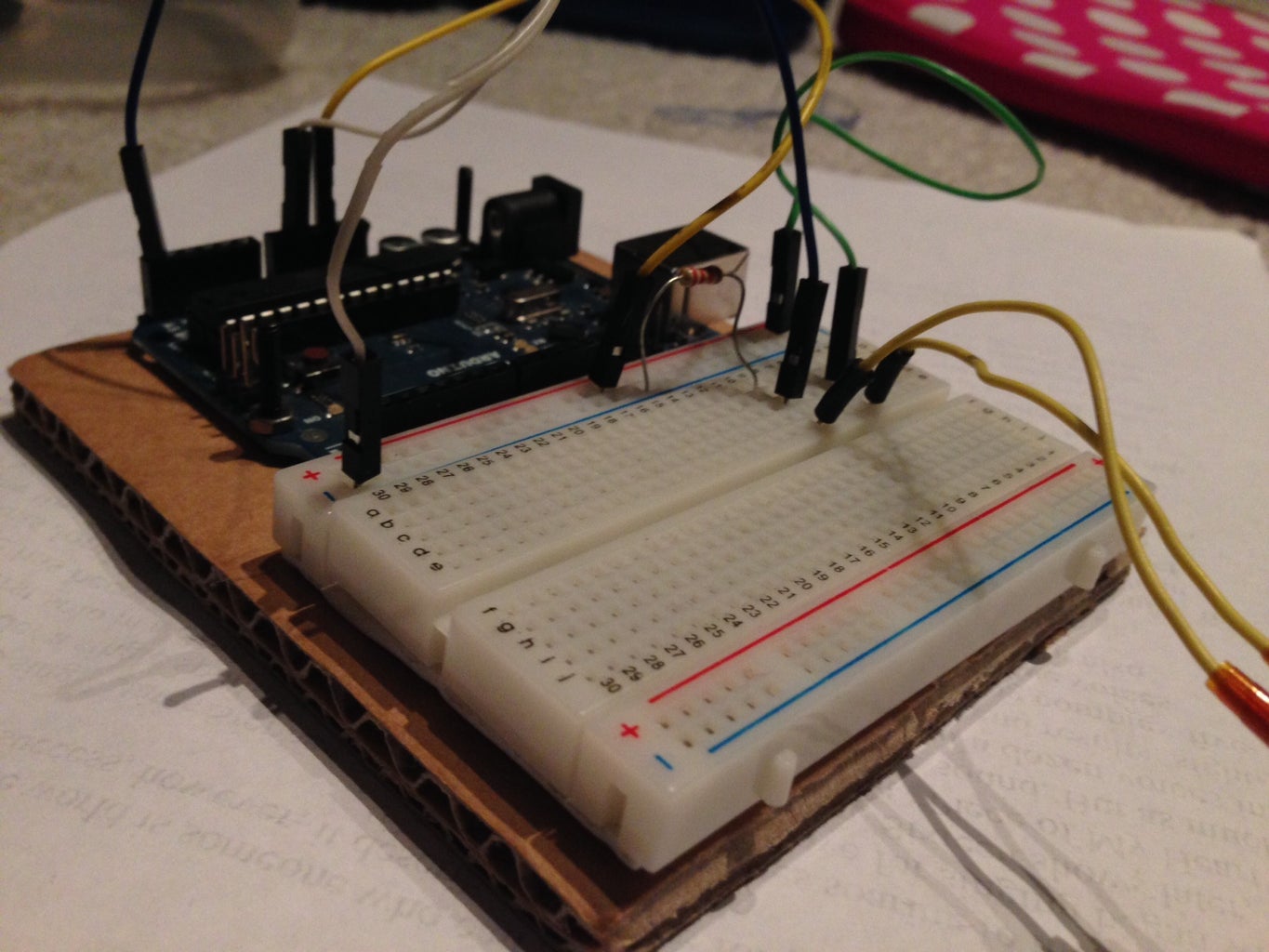
Building Automation System using TEMPERATURE SENSOR AND GAS SENSOR Circuit Diagram Do NOT use the sensor inside the CPU chip to guide the case ventilation fans. The never let the mobo take control of graphics card cooling, and hence normally do not send any temperature info to the mobo. In the end, I just left it linked to the CPU sensor. The temperature controller is more than fast enough to keep up with the CPU The Computer Temperature Sensor reads temperature data from all Intel Core based processors. It has the ability to individually balance or adjust real temp for each core of your CPU. There will be features like high temperature alarm and feature based on CPU and an Arduino is an open-source electronics platform based on easy-to-use hardware board designed around an 8-bit Atmel AVR

These placements generally give the most stable and accurate temp of how hot the entire system is running — compared to something like the CPU package temp that may erratically spike up and down or the coolant temp that may not correctly reflect the additional heat generated by non-CPU components (like the GPU) — thereby making it the ideal

ESP32 Internal Temperature Sensor Circuit Diagram
We can use Thingspeak as a cloud service provider and DHT11 to measure temperature and humidity. After reaching a particular temperature relay can turn ON or OFF cooling system connected to it i.e So, we can't use it to measure the ambient temperature (the temperature of the atmosphere), for that, we need to use embedded temperature sensors i.e. DS18B20, DHT11, BMP280 etc. We will first discuss the basics of this Internal Temperature Sensor and then will design a code to monitor the change in temperature by changing the frequency of the d. Verify you now have a CPU temp sensor by going to Settings->Devices & Services->Entities, search for CPU Temp, click on it and view the CPU temp under the info tab. Add the fan control. For this example, I have my PI 4B PWM controllable fan's TXD cable connected to GPIO-14. a. Edit the config/configuration.yaml b.
Creating an Arduino-based PID-controlled temperature system can add precision and automation to many temperature-sensitive projects. By using a MOSFET instead of a relay to control a 12V fan, we gain smoother control over fan speed, allowing us to maintain a consistent temperature. LM35 Sensor: Connect the LM35 as follows: VCC to 5V on the

Best mobo temp sensor to use for case fans Circuit Diagram
Learn: How to control temperature using ESP32, fan and DHT11 or DHT22 sensor. The detail instruction, code, wiring diagram, video tutorial, line-by-line code explanation are provided to help you quickly get started with ESP32. Find this and other ESP32 tutorials on esp32io.com.
Some of these uses active cooling method, by using a fan on heatsink which help to remain the temperatures more stable. But when running these things on a low power fan is still on and feel noisy. So why not to make a programmable fan which can be turned on when required. Using Arduino and temperature sensor we can make a temperature-controlled

Proper temp sensor probe placement for controlling AIO ... Circuit Diagram
In this article, you are going to learn about Arduino temperature controlled fan using DHT22 sensor and relay. We will use the DHT22 sensor to get the temperature value and we will print this temperature value on the LCD. Then we will check if the temperature value is greater than 35 or not, if the temperature will be greater than 35, then the
