Circuit diagram of the LED matrix Similarly now if I take 2 LEDs and short their cathodes this will make 1X2 Matrix and If I add another row to it it will make 2X2 matrix but this time we will short all the cathodes of the LED row-wise and anode column-wise. Using the same concept we are going to make a matrix which consist of 6 rows and 24 columns
For each 8x8 matrix (64 LEDs), you will need one MAX7219-based driver. My recommendation: Buy an additional 3 or 4 LEDs per every 64 LEDs, just in case. For my 64x8 matrix I needed: Eight MAX7219-based drivers; 512 LEDs; Dozens of feet of wire; Five boards. Besides the matrix itself, I also needed one ESP-8266 to control the matrix.
DIY LED Matrix : 8 Steps Circuit Diagram
An LED Matrix can be used in sign boards with scrolling messages, display animations, synchronized music spectrum, etc. It is really fun to build an RGB LED Matrix as it involves different aspects like circuit design, constructing the matrix, assembling the components and coding. In this tutorial, we will show you how to make you own 8×6 RGB

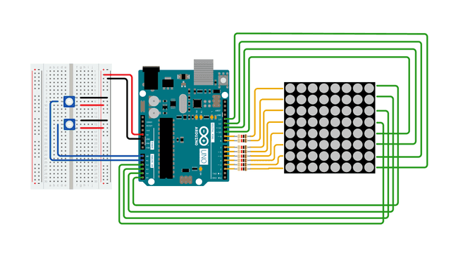
Use the circuit figure below to connect the Arduino LED matrix together. Then, take the positive lead of the first LED and bend it down to the other LEDs and solder the pins which touch each other. Next, take the last lead that you soldered and bend it again down and repeat till you have all the positive leads connected in the column. The circuit diagram of the 7×5 LED matrix display using Arduino is shown in figure 1. The entire circuit of LED matrix is built around Arduino uno board, few NPN bipolar junction transistors (7 nos. in 7×5 display), a few numbers of resistors (equal to the number of transistor i.e. 7), and LEDs (7×5 = 35 nos.). Character LCD displays, LED matrix displays, and seven segment displays are perfect for showing sensor data, menus, and status messages. LEDs can be used as status indicators, and buzzers can serve as sound alarms when a sensor reading gets too high or low. Pick a tutorial below to learn more!

DIY LED Matrix Display With Arduino Circuit Diagram
Applying this knowledge, to light the top-right LED (A,4) in a common-row cathode matrix you would feed positive voltage to column 4 and connect row A to ground. We will be building this arrangement of common-row cathode matrix in this tutorial. Step 1: The Parts To build this matrix, we will need a few things to get us started.

Learn how LED matrix works, how to connect LED matrix to Arduino, and how to program Arduino step by step. Detailed instructions, code, wiring diagram, video tutorial, and line-by-line code explanation are provided to help you quickly get started with Arduino. Before diving into the how, let's talk about the why. Why should you spend time building an LED matrix display? Creative Freedom: Whether you want to display text, patterns, or animations, an LED matrix lets you express yourself creatively.; Learn Electronics: This project helps you understand concepts like multiplexing, addressing, and circuit design. In this video we will see how to set up and program LED matrix displays on the Arduino, how to scroll text across the display, how to print the readings from
