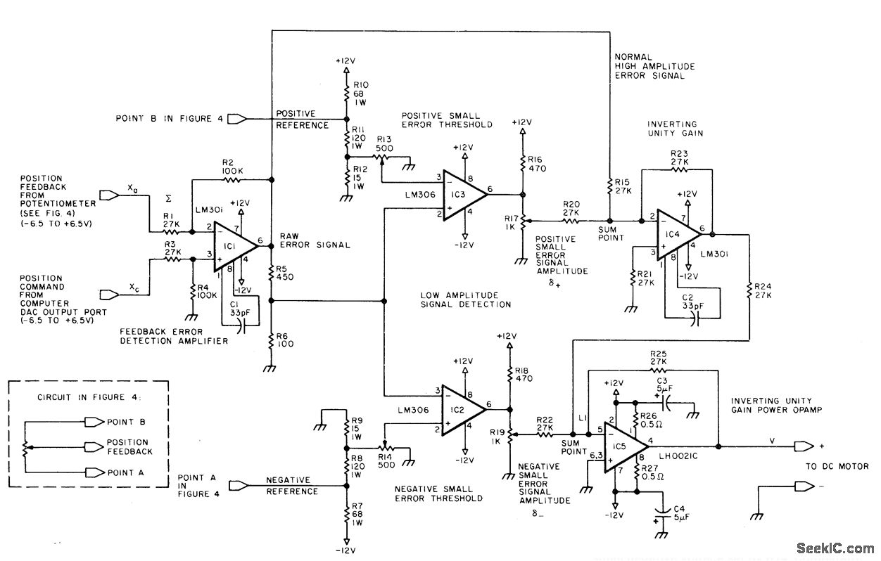
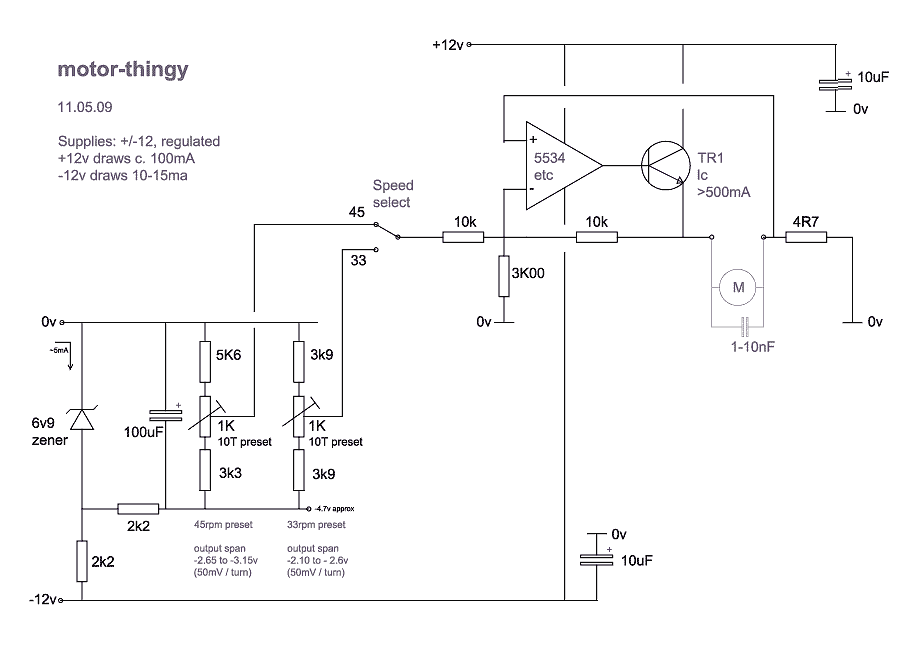
DCMOTORCONTROL Circuit Diagram Hello Guys today in this video I will show you How To Make Simple DC Motor Speed Controller Circuit Check the electronic components you need here: https://ww The main feature of the DC Motor Speed CONTROL is a 555 IC-based PWM circuit, designed to obtain variable voltage over constant voltage. Here is the procedure for PWM. Take a simple circuit, as seen in the following diagram. This is a simple pulse width modulation speed controller for a DC motor which uses one of these, a 555 timer, and we're going to show you how the circuit works, how to design one and even turn it into a professional looking printed circuit board.

In this instructable, I'll demonstrate a simple and inexpensive circuit that controls a DC motor from two I/O pins. It requires no integrated circuits, and uses commonly available parts. I recommend you build it on a breadboard the first time. I designed this circuit, but I'm not the inventor of this type of motor controller. Making a circuit to control a DC motor speed may look easy, but having a circuit which can provide enough torque to the motor even at lower speeds may not be so simple. In this post we discus how to build a simple DC motor speed controller circuit which can provide sufficient power or torque to the motor even at slower speeds.

Speed Controlling of DC Motor Using MOSFET Circuit Diagram
Introduction. A direct current (DC) motor is the oldest type of electrical motor that has gained widespread use in a variety of electronic devices and equipment.DC motors have different arrangements and operation peculiarities. The common feature and the essential condition of all DC motors is the generation of a variable magnetic field that provides their non-stop operation. Here's the simple circuit diagram for controlling a DC motor's speed using an Arduino and a MOSFET. This minimal-component design is easy to understand. For direction control, check out our L293D project. Circuit Diagram Overview: Components: Arduino UNO, MOSFET, 1k Ohm resistor, 10k Ohm potentiometer, diode, 12V power supply. Connections: The next figure below shows a very simple DC motor speed controller circuit that employs a MOSFET as a high-power potentiometer (rheostat). The circuit is designed to work with 12 volt DC motors having a peak current usage of below 5 amp.
