DIY Miniature Solar Tracker 5 Steps with Pictures Circuit Diagram Arduino Solar Tracker Complete circuit diagram; Step by Step soldering; Complete interfacing; step by step Arduino Solar Tracker program explanation; Finally testing. Today the solar trackers are used throughout the world, the solar tracker that we are going to make today is best as it's cheap and is able to rotate heavy panels as we will be This is a fully functional portable solar tracker design. If there is enough interest in such a device as a DIY project - we will post complete step by step
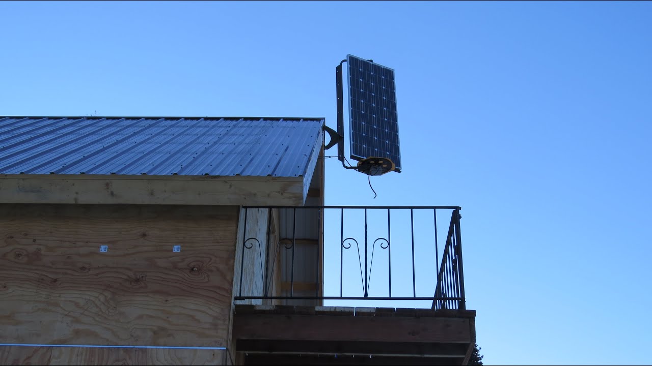
As soon as the sun rises above the horizon, power goes from zero to full in about twenty minutes. Solar output sits at constant full power for about sixteen hours, then quickly drops to zero, again in about twenty minutes. Assuming a clear blue sky all day of course. That is pretty much what a moving tracker is supposed to do.

Smart GPS Tracker Using Arduino Circuit Diagram
This video will guide you with making your own GPS tracker over GPRS that runs on battery and also the battery get's charged with the Solar Panel connected w Today, we're going to build a smart gps tracker using Arduino that can help you keep tabs on your child's location - and as a bonus, it can also be used for tracking vehicles or other valuable items.. As parents, ensuring the safety of your child is always a top priority. Questions like 'Has my child safely reached school?', 'Are they home alone?', or 'Are they at the

Notice that the LiPo battery is the primary power source for the FONA and Arduino board. The V15 battery keeps that topped up. Also, make sure to manually switch the button on the FONA board from charge to power mode. Lastly, properly install the SIM card (we used Ting from the Adafruit site) as well as both the GSM and GPS antennas. Software: Hello everyone, I'm working on a dual-axis solar tracker project to maximize solar energy efficiency, and I'd like to share my setup and plans. The system uses light-dependent resistors (LDRs) to track the sun's position and adjust a solar panel via servo motors. Additionally, real-time voltage and current from the solar panel will be logged and displayed on a mobile app using a
Time Data Monitoring and ... Circuit Diagram
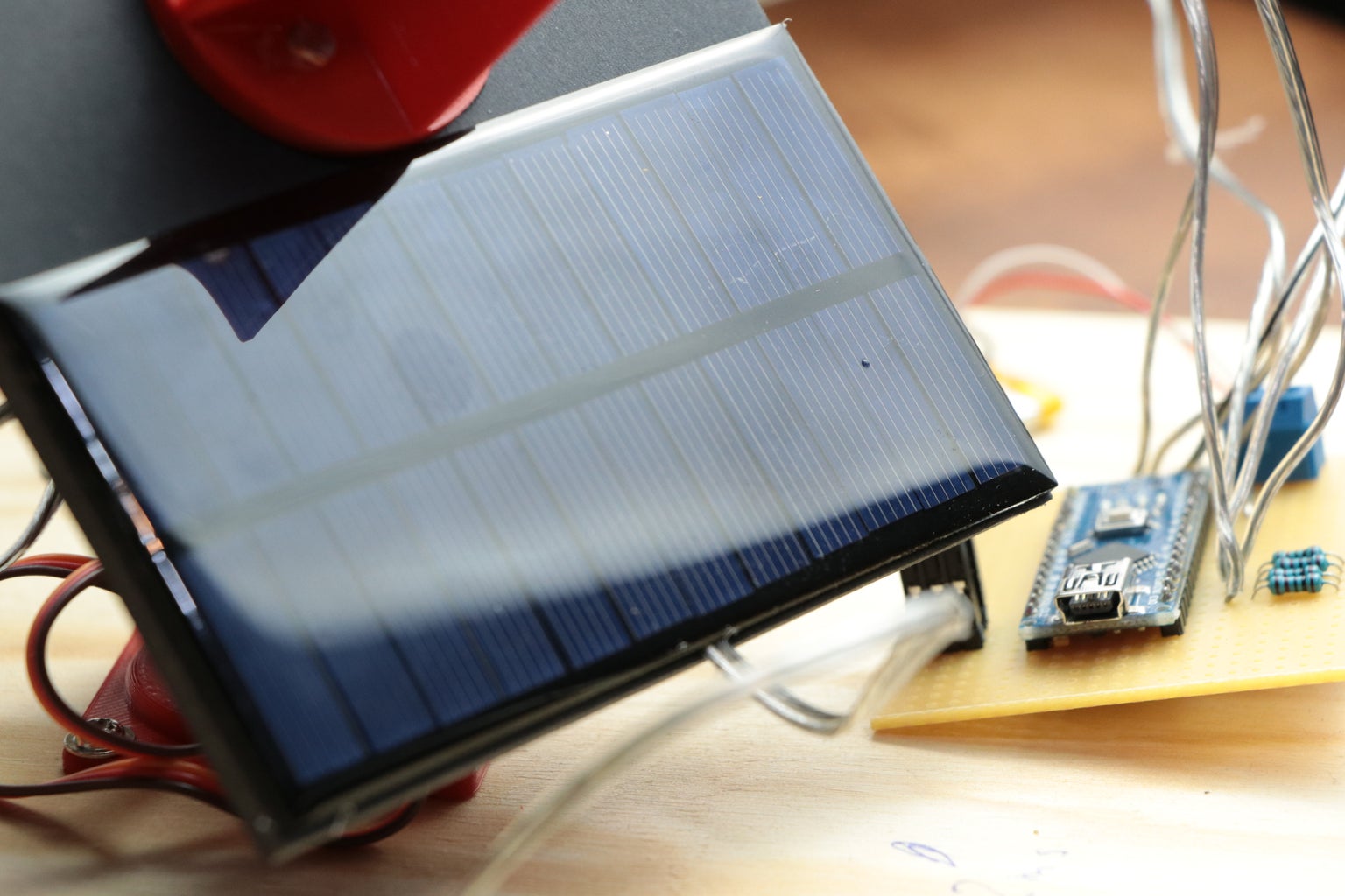
Hook the Volt Meter and Solar Cell together via the unused spots on the 4 Port Terminal Block. The Volt Meter's White and Red Wires connect to the Red (Positive) wire from the Solar Cell. Then connect the Black wire from the Solar Cell and Volt Meter. The Volt Meter we're using is powered directly from the Solar Cell. Save the 'GPS_Tracker' sketch folder as pictured above to any destination you like. Double click on 'GPS_Tracker.ino' to open the IDE. Ensure that the connection to your TinyDuino is configured properly, turn on your TinyDuino, and hit upload. Open the Serial Monitor to ensure that your device is outputting properly. 1) Choose whether you want Helios to act like a solar panel and track the sun (set the variable heliostat=0) or a heliostat (set the variable heliostat=1) a. Note: We suggest that you try it as a solar panel first to make sure that it moves how you expect. If one of the axis seems to be off, then you may have put in one of the servos backwards.
