Figure 1 from Development of health monitoring system using smart Circuit Diagram Then upload the code to the Arduino UNO by assembling the circuit shown above. Open the serial monitor and it will automatically connect to Wi-Fi and set up everything. Now click on channels so that you can see the online data streaming, i.e IoT Based Patient Health Monitoring System using ESP8266 & Arduino as shown in the figure here. Now we demonstrate how to build an IoT-based patient health monitoring system using the ESP32 microcontroller and the Blynk app. This project is designed to continuously monitor vital health parameters like heart rate, body temperature, and oxygen levels. The data is sent to the Blynk app in real time, allowing remote monitoring from anywhere.
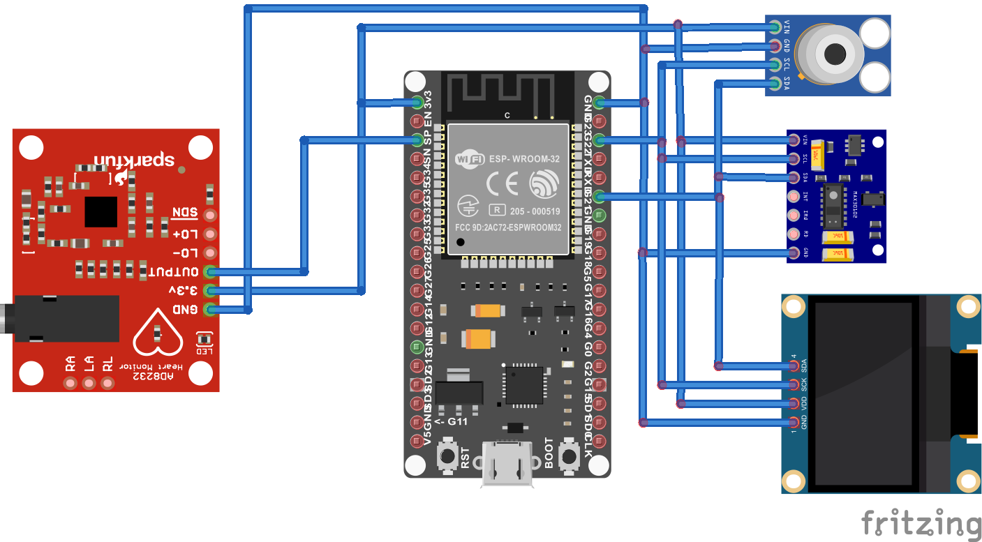
So taking this scenario into account we came up with an idea to build a remote health monitoring system which can transmit the health data to the cloud servers, According to the above circuit diagram all the connections between ESP8266 and Sensors are explained below. Interfacing GY-MAX30100 and ESP8266 NodeMCU. VIN -> Vin (5v) IoT based health monitoring system circuit diagram interfacing sensors with ESP32. Now lets connect all the required components according to the below schematic diagram. As you can see from the above circuit diagram of IoT based health monitoring system project, we connected 3 sensor which gives 5 health parameters as we discussed in the The circuit diagram of IOT based Patient Health Monitoring system is shown in the figure below. If you are doing the same project then assemble the circuit as shown in the figure below: CIrcuit Diagram Of Patient Health Monitoring Based On IOT. Connect Pulse Sensor output pin to A0 of Arduino and other two pins to VCC & GND.

IoT Based Patient Health Monitoring System Using ... Circuit Diagram
In this project, we will learn how to build an IoT-based patient health monitoring system using ESP8266/ESP32.We can measure Heart Rate/Pulse (BPM) as well as Blood Oxygen Level (SpO2) using the MAX30100 /102 pulse oximeter sensor.We use the DS18B20 temperature sensor to measure body temperature. Similarly, the patient needs to be kept in a room having a certain temperature and humidity level.
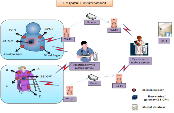
The proposed project can collect and send patient's health data IoT based health monitoring system | Arduino Project IoTbased patient health monitoring system using Arduino and generic ESP8266.

IoT Based Patient Health Monitoring System Using ESP8266/ESP32 Circuit Diagram
Here in this project, we will make an IoT based Health Monitoring System which records the patient heart beat rate and body temperature and also send an email/SMS alert whenever those readings goes beyond critical values. Pulse rate and body temperature readings are recorded over ThingSpeak and Google sheets so that patient health can be Circuit design SMART HEALTH MONITORING SYSTEM created by Ananya Sharma with Tinkercad Circuit design SMART HEALTH MONITORING SYSTEM created by Ananya Sharma with Tinkercad SMART HEALTH MONITORING SYSTEM. 0 . Simulate. This is a remix of Copy of SMART HEALTH MONITORING SYSTEM _ m_and_i_project by 245-wildan Firdaus. Delete image . Real-time remote Health monitoring system with critical health metrics such as heart rate, SpO2, body temperature, and ECG data, which could benefit both patients and healthcare providers. Powered by Arduino UNO R4 WiFi and IoT Cloud, this solution demonstrates how affordable microcontrollers and sensors can be leveraged for real-world health applications.