Gps Tracking Circuit Diagrams The GPS monitors and relays data to a server through a cellular or satellite network. In this project, we'll design a vehicle tracking system using Arduino, SIM900A GSM/GPRS modem, and the Neo 6M GPS module. The device will transmit a vehicle's real-time location using the ThingSpeak server. Download this code, and use it with your GPS. RX --> Digital pin 10, TX --> Digital pin 11. Note: Don't forget to use the module outdoors, preferably when there is no cloud. After half a minute, the device should blink and output your GPS coordinates! :) Once, you know that your SIM800L and GPS module are working adequetly, you can go onto the b. Sending the GPS data from Raspberry Pi to the webpage. a. Making a Realtime geolocation tracking webpage: So let's make the webpage first. So here we will use a API called PubNub, which is used to deliver realtime data. Here we will use this to send our GPS data from Raspberry Pi to our webpage. We are using this API for three reasons:
Applications of GPS Module with Arduino. Now that you know how to interface GPS module with Arduino, you can explore several practical applications: Vehicle Tracking System: Monitor real-time location data of vehicles. Personal Tracking Device: Create a wearable GPS tracker for individuals. Drone Navigation: Use GPS data for precise drone In this article we are going to implement a real time location tracking system with NEO GPS and a SIM800 GSM module. This is for the intention to track location of your vehicle or any other thing that you want to track and want to know the position on your mobile phone. This code-centric guide demonstrates how to build an Arduino GPS A GPS Tracker Using Arduino UNO, SIM800C, and Neo-6M-GPS Modules: This tutorial is part of the Internet of Tricks Erasmus+ Project. By the end of the tutorial, you will create a GPS Monitoring Device that can track users in almost real-time. The device has pedagogical purposes and is designed to increase user awar…
Build a GPS live tracking system Circuit Diagram
Save the 'GPS_Tracker' sketch folder as pictured above to any destination you like. Double click on 'GPS_Tracker.ino' to open the IDE. Ensure that the connection to your TinyDuino is configured properly, turn on your TinyDuino, and hit upload. Open the Serial Monitor to ensure that your device is outputting properly.

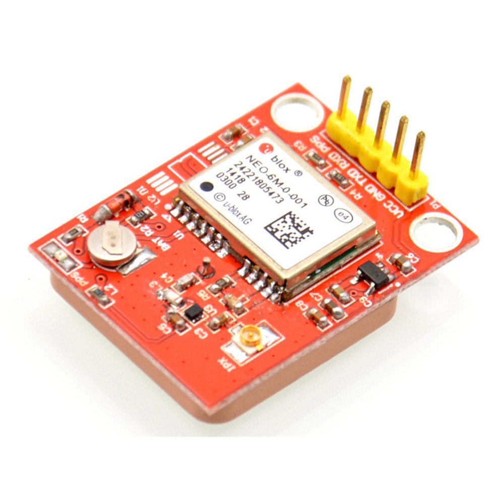
The L86 has a patch antenna on top measuring 16.0mm × 16.0mm × 6.45mm, with 66 acquisition channels and 22 tracking channels.It acquires and tracks satellites in the shortest time even at the indoor signal level. The module operates at 2.8V~4.3V with a typical power consumption of 20mA and in Standby mode power consumption is around 1.0mA.To learn more about the L86 GPS module, you can check In this article we are going to see how to use Neo 6M GPS module with Raspberry Pi and also how to use python to process the GPS data. Hardware Part: So at first lets talk about the hardware part. Here I will use Raspberry Pi 3 B+, but You can also use other varients like Raspberry Pi Zero, Raspberry Pi 4 etc. For tracking the device and display the position in real-time on a map, we will use Mapbox and Javascript powered EON Dashboard. The full code can be found here. To start you will need to create a MapBox account. Once this is done, you can either create a new map design or use an existing one for example Mapbox streets.