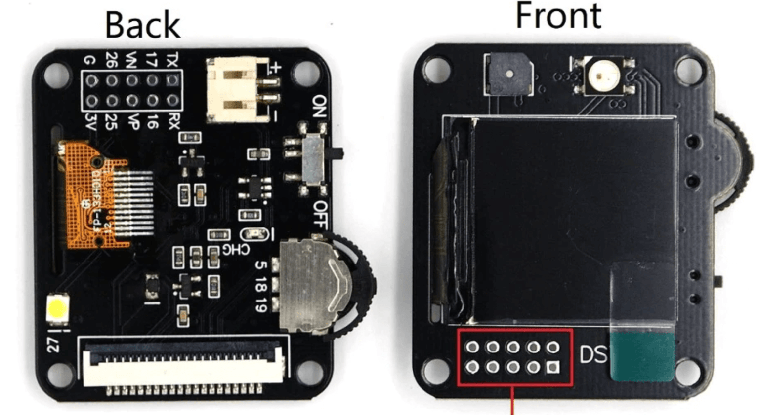
HELTEC Wireless Tracker Support Meshtastic based WIFI ESP32 Circuit Diagram In this project, we are going to learn how to create an IoT based health monitoring system using ESP32 Microcontroller with built in WiFi and Bluetooth to display health data such as: Patient body Temperature, Patient Blood Oxygen(SPo2), Patient Heart rate, Room Temperature; Room Humidity; and more (optional). This IoT health monitoring with LoRa technology project design that uses ESP32 board to read a DHT11 sensor for human temperature and skin humidity. It also reads the pulse rate of the person. using a pulse sensor module. The ESP32 is connected to a LoRa module, Sx1278, so that it can form a transmitter side. Wearable fitness trackers have revolutionized personal health monitoring, making it easier to track physical activities, heart rate, and overall fitness goals. This guide provides a detailed step-by-step approach to creating a wearable fitness tracker using the ESP32, starting from component selection to programming and final assembly.
The portable health monitor tracks a user's pulse rate, oxygen level, body temperature, and heart rate. ESP32 receives the raw ECG value from the output terminal of the AD8232 ECG sensor. This value is obtained at the analog input pin of ESP32. The MLX90614 and MAX30100 sensors communicate their values through the I2C interface.

ESP32 based Patient Health Monitoring System Circuit Diagram
In this project, we will learn how to build an IoT-based patient health monitoring system using ESP8266/ESP32.We can measure Heart Rate/Pulse (BPM) as well as Blood Oxygen Level (SpO2) using the MAX30100 /102 pulse oximeter sensor.We use the DS18B20 temperature sensor to measure body temperature. Similarly, the patient needs to be kept in a room having a certain temperature and humidity level. Now we demonstrate how to build an IoT-based patient health monitoring system using the ESP32 microcontroller and the Blynk app. This project is designed to continuously monitor vital health parameters like heart rate, body temperature, and oxygen levels. The data is sent to the Blynk app in real time, allowing remote monitoring from anywhere. Source Code/Program Explanation. The Program code for the ESP32 based Patient health monitoring system starts by including the following libraries: WiFi.h and WebServer.h library are used for connecting the ESP32 board to the Wi-Fi network and setting up a webserver.Wire.h library is for communicating any I2C device not just the MAX30100 Pulse Oximeter sensor.

By leveraging the ESP32, a robust microcontroller with integrated Bluetooth and Wi-Fi, you can develop a compact and effective wearable health monitoring device. This guide walks you through the process of creating a health monitor to track heart rate and blood oxygen levels, providing real-time data to users or healthcare providers.

IoT Based Health Monitoring system on ESP32 Web Server Circuit Diagram
ESP32 is a small system on-chip microcontroller integrated with Wi-Fi and dual-mode Bluetooth. It has been used to create various low-cost and low-power wearables. If you're feeling creative and want to try making your own smartwatches, you're in the right place. Let's look at some of the coolest ESP32 wearable projects that have been made. 1. Overview. With tons of new healthcare technology start-ups, IoT is rapidly revolutionizing the healthcare industry. Keeping track of the health status of your patient at home is a difficult task because of the busy schedules and our daily life work. Specially old age patients should be periodically monitored. So we propose an innovative system that automated this task with ease.
