How does an inductor work Circuit Diagram By understanding these applications, you can better appreciate the fundamental role of inductors in various electronic systems. Inductor Characteristics. Understanding the characteristics of inductors is crucial for effective circuit design and troubleshooting. Two key aspects are impedance and inductive reactance. Impedance and Inductive Reactance

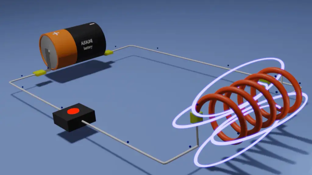
Learn about the role of inductors in electrical systems and how they store energy in a magnetic field. These components are common in electronic circuits, power supplies, and applications that require filtering, energy storage, or impedance control. Understanding the function of these components, the different types, and their Understanding the Basics of Inductors An inductor is a fundamental component in electrical and electronic circuits. Its primary function is to store energy in the form of a magnetic field when an electric current passes through it. Inductors are typically made by winding a coil of wire around a core material, such as air, iron, or ferrite. These principles can be applied to filter and coupling circuits. However, you must first understand the traits of reactance and how they change as a result of inductance and frequency of the applied voltage. Figure 3. As inductance increases, inductive reactance also increases. Power in Inductive Circuits
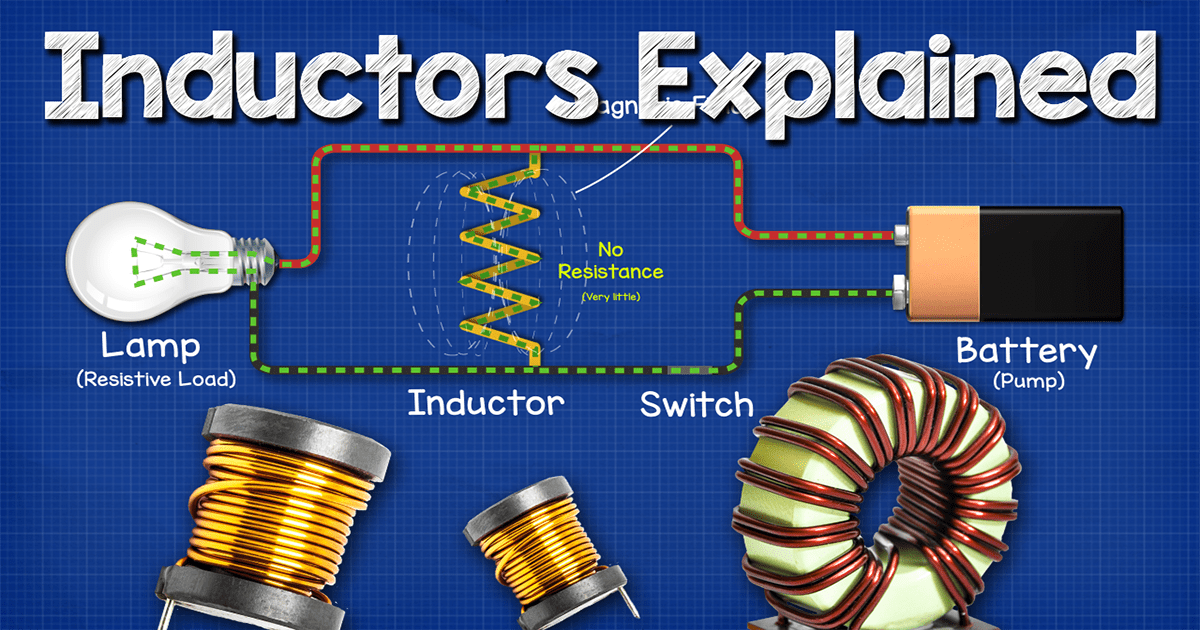
What Does an Inductor Actually Do? Why Do We Have Inductors in Circuits? Circuit Diagram
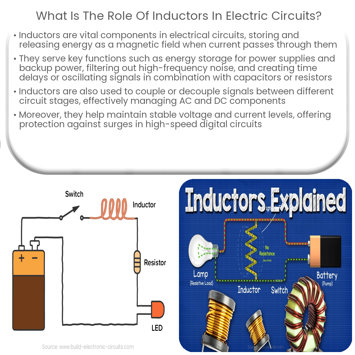
One reason to include an inductor in a circuit is to protect the circuit from current spikes (i.e. as a surge protector). If the current changes dramatically and suddenly, then the inductor will respond by providing an emf that opposes the sudden change, reducing the amount that the current is able to change over a short period, protecting the Inductors are fundamental components in electrical circuits, playing a crucial role in shaping the behavior of electrical signals. Understanding what an inductor actually does and why we have inductors in circuits is key to grasping how modern electronic devices function. In transient DC circuits, or circuits where you're measuring what happens in a short period of time after a change, inductors are a little more complicated. Inductors resist changes in current, so if there is a switch that closes and the voltage across an inductor changes from 0V, the voltage will try to change instantaneously but the current

Schematic Symbols: In circuit diagrams, inductors are represented by a coiled wire symbol, with variations indicating air-core, iron-core, or variable inductors. Recognizing these symbols helps in understanding circuit functions and identifying the role of each inductor within the system. Series and Parallel Inductor Configurations They play a crucial role in modern circuits and are constantly adapting to fit the needs of the digital age. With new materials, designs, and manufacturing processes, designers are overcoming challenges faced by traditional inductors. As technology continues to advance, so will the development of inductors, making them an integral part of
5.4: Inductors in Circuits Circuit Diagram
As above, iron in inductors takes the form of an iron core. They are typically used for low frequency line filtering due to their relatively large inductances. They are also used a lot in audio equipment. Inductors don't always need to have an iron core, though. Air core inductors. Figure 3. An air core inductor manufactured by Wurth Elektronik.