How to Capture Temperature and Humidity Using the ESP8266 Weather Kit Circuit Diagram ESP8266-based simple fridge temperature controller with Web GUI - eltomek/esp8266-fridge. ESP8266-based simple fridge temperature controller with Web GUI - eltomek/esp8266-fridge add support for linear temperature control (e.g start at 17 degrees Celsius and finish at 21 after 5 days) - might be awkward with no RTC onboard; Hello and welcome to this tutorial, on how to build an IoT Based Temperature Control & Monitoring System using ESP8266 & Blynk 2.0 with two manual and automa While the defrost timer in my garage fridge is starting to fail, I have been giving some serious thought about converting it to running off an esp8266. This is an older GE side by side (circa 1995 when new). The ESP would need to run a single relay to replace the defrost timer, switching between compressor and defroster about every 16 hours (16 hours compressor run, 15 minutes defroster run
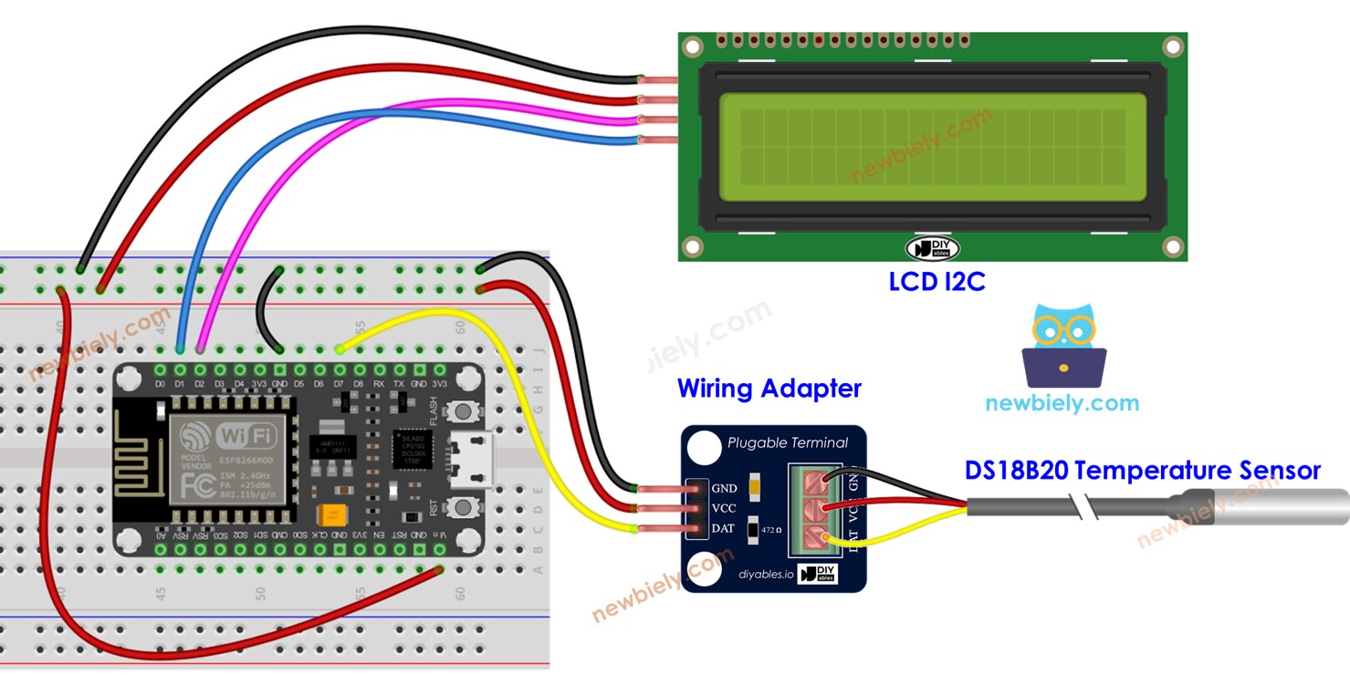
First, connect the OLED display to the ESP8266 using I2C (SCL & SDA) pins. Next, connect the DS18B20 Dallas temperature sensor to the ESP8266 D7 pin. Add a 4.7k ohm resistor between DQ and VDD pin. Then, connect the two-channel relay to the ESP8266 D5 and D6 pins.While VCC is connected to the Vin pin for a 5V power supply. Connect all GND pins to GND and VCC or VDD pins to the 3.3V pin of the In 2005 a smart medical refrigerator concept was proposed which monitors the medical requirements of patients and dispenses medicines or notifies relatives or doctor if medication is not taken by the user[8]. A paper was proposed intending to provide better nutrition to the users by the use of smart refrigerator[9] the

based simple fridge temperature controller with Web GUI Circuit Diagram
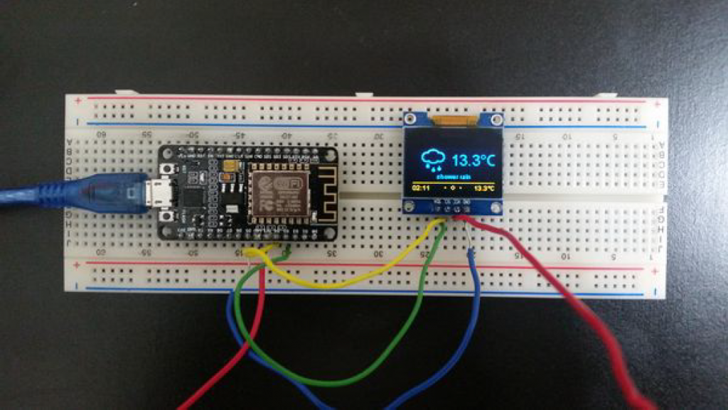
The temperature control system has a wide range of applications, from HVAC (Heating, Ventilation, and Air Conditioning) systems to industrial processes.In this tutorial, we will demonstrate how to build a temperature control system using an ESP8266 microcontroller, DS18B20 temperature sensor, and an OLED display.We will also use the ESPDash Library with AsyncWebServer library to set up a web The code for the IoT-enabled Smart Fridge with ESP8266 WebServer is written in Arduino IDE. This code sets up a smart Fridge using an ESP8266 microcontroller. It connects to a Wi-Fi network, reads temperature data from two DS18B20 sensors, and monitors battery voltage to calculate the battery percentage.
In this article, you will learn how to convert any Fridge or Refrigerator into a smart internet of things based Fridge or Refrigerator using a Push Button or a limit Switch, Nodemcu ESP8266 Wifi Module, a variable resistor, DS18b20 one wire waterproof digital temperature sensor capable of measuring the temperature from -55C to 125 Centigrade
PDF Implementation of Smart Refrigerator based on Internet of Things Circuit Diagram
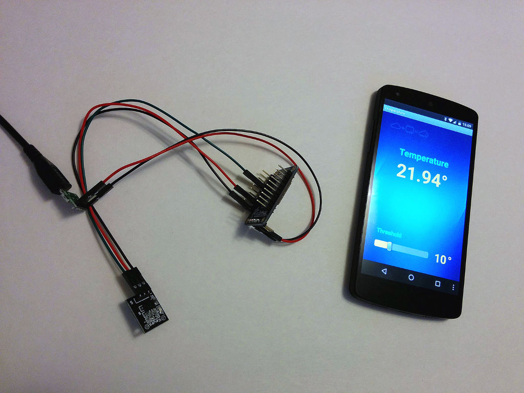
Connect your ESP8266 board to power and ensure it is connected to the Wi-Fi network. Open the Blynk app on your mobile device and navigate to the project dashboard. Use the widgets to control the LEDs, monitor connectivity, and view temperature readings. Test different scenarios and functionalities to ensure proper operation.
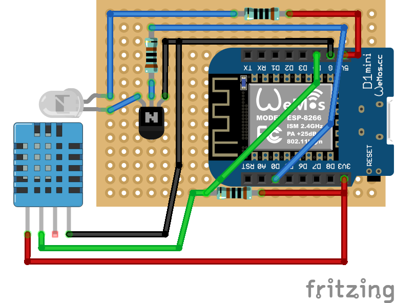
The main motto of this project is to make a prototype of an IoT Based Smart Kitchen using the Internet of Things.The system uses multiple sensors, relays & NodeMCU ESP8266 Board. We can monitor all the sensor data on Blynk Applications.We can also send the command from Blynk App to control Kitchen Appliances.
