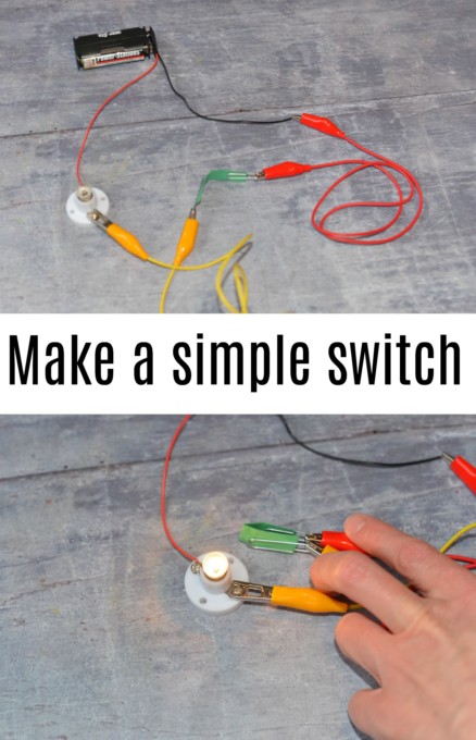
How to make a simple switch Circuit Diagram Introduction to Switch Circuits. A switch circuit is a fundamental component in electronics. It allows you to control the flow of electricity, turning a device on or off with a simple flick of a switch. This might sound basic, but it's the foundation for more complex circuits and projects. So, let's start with the basics. What You'll Need Attach this piece of wire to the second terminal on the switch. This will again complete the circuit. Unlike in the previous experiment, this will not complete the circuit and turn the bulb on. In order for that to happen, you have to flip the switch! When you attach the switch to the circuit, make sure the switch is off (open).
In the circuit that i build thats not totally the same as the in the diagram, is suppose to turn on the led at 8V because i used a 5v and 3v zener. I also used a two 9 V batteries which voltages differ. The circuit i suppose to turn the led on at 8 V and any voltage lower than it should go off. A switch is basically a mechanical device that creates a. break in a circuit. When you activate the switch, it opens or closes the circuit. This is dependent on the type of switch it is. As switches get more complex they can both open one connection and close another when activated. This type of switch is a single-pole-double-throw switch (SPDT).
3 Ways to Make a Circuit Circuit Diagram
Simple Electric Circuit using substitute materials. You may not have access to battery holders, lamp holders and switches. In that case you may still be able to make a simple electric circuit. In this method we use thumbtacks, paperclips, clothespin, rubber band to substitute conventional materials such as switch, battery holder and lamp holder. An nMOS transistor works like this: When a voltage higher than the transistor's threshold voltage (V TH) is applied between the gate and the source, a current can flow from the drain to the source, making the transistor work as a closed switch. If 0V is applied to the gate, no current will flow, so the transistor will behave like an open switch. This circuit is most impressive when the wires are long, as it shows how the switch is able to control circuit current no matter how physically large the circuit may be. Step 2: Measure voltage across the battery, across the switch (measure from one screw terminal to another with the voltmeter), and across the lamp with the switch closed and

In this video you will learn how to build a Simple DC Load Toggle Switch Circuit. This circuit allows you to easily turn ON/OFF any DC load. You can also rep To make a simple electrical circuit with a battery, use wire strippers or scissors to strip the ends of a length of insulated wire, but do not cut all the way through the wire. Install your batteries in a battery pack, then attach your wires to the battery pack using a battery snap or electrical tape.
