Led Matrix Display Panel Circuit Diagram An RGB LED Matrix is one such project which many students and hobbyists put it on their to-do list of Arduino Projects. An LED Matrix can be used in sign boards with scrolling messages, display animations, synchronized music spectrum, etc. It is really fun to build an RGB LED Matrix as it involves different aspects like circuit design Applying this knowledge, to light the top-right LED (A,4) in a common-row cathode matrix you would feed positive voltage to column 4 and connect row A to ground. We will be building this arrangement of common-row cathode matrix in this tutorial. Step 1: The Parts To build this matrix, we will need a few things to get us started.
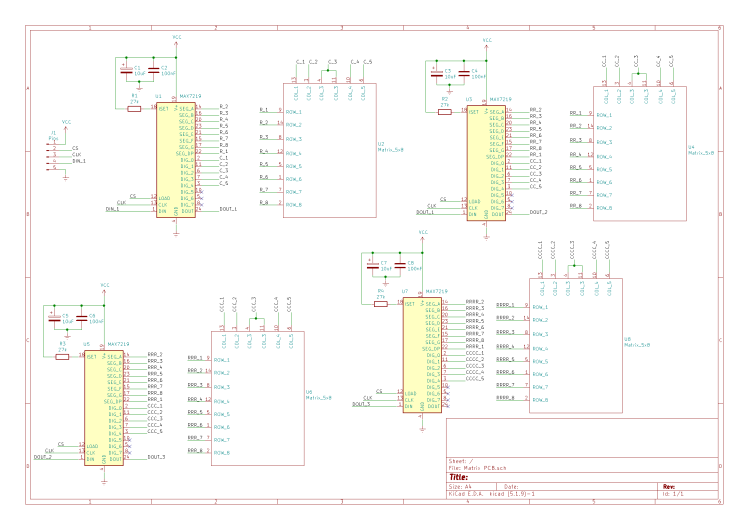
The objective of this post is to explain how to create a simple LED Matrix using PNP transistors and a ULN2803A integrated circuit. We will assume that only one LED (or none) needs to be connected at each time. First of all, we need to take into account that, if we wanted to control a matrix with a total of X LEDs and to be able to control each We kick things off by designing the circuit schematic using Altium Designer.The heart of our LED matrix is the versatile MAX7219 display driver, capable of driving the LED matrix efficiently.This driver uses SPI communication, requiring only three Arduino pins to control all 64 LEDs in the matrix.I carefully placed 64 LEDs in an 8 by 8 matrix layout, ensuring proper connections for the MAX7219
LED Matrix Display using Arduino Circuit Diagram
LED matrix display, also known as LED display, or dot matrix display, are wide-used. In this tutorial, we are going to learn: LED matrix. Howerver, please do not copy the content to share on other websites. We took a lot of time and effort to create the content of this tutorial, please respect our work! Use the circuit figure below to connect the Arduino LED matrix together. Then, take the positive lead of the first LED and bend it down to the other LEDs and solder the pins which touch each other. Next, take the last lead that you soldered and bend it again down and repeat till you have all the positive leads connected in the column. Circuit Description of LED Matrix Display using Arduino: The circuit diagram of the 7×5 LED matrix display using Arduino is shown in figure 1. The entire circuit of LED matrix is built around Arduino uno board, few NPN bipolar junction transistors (7 nos. in 7×5 display), a few numbers of resistors (equal to the number of transistor i.e. 7

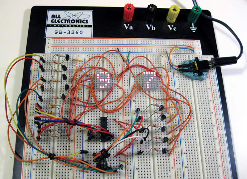
It's shown in the circuit that a single shift register is used to control the 8 rows and for controlling the columns, we use one shift register for each 8 columns. Let's build a simple 8 x 8 scrolling display on the breadboard. The circuit is split in to two parts - row control and column control. Let's build the column control first.
