LTC4000 LiFePO4 battery charger circuit design Circuit Diagram battery packs. Figure 1 illustrates a charge cradle that can range from one cell to 'n' cells batteries. Each power path has one IC (Integrated Circuit) to manage the charge profile and display the state of charge. Most LiFePO4 battery manufacturers have different charge and discharge specifications for their batteries.

Here LiFePo4 Battery charger circuit designed by using IC TP5000 to charge 3.2V battery. The TP5000 battery charger circuit is a simple and efficient solution for charging single-cell Li-Ion/Li-Po batteries. It provides a safe and reliable charging process with built-in safety features. When using this circuit in your projects, always follow How to make a 12V LiFePO4 battery charger from a 15V/25A low cost power supply unit. Learn how to modify a fixed voltage output (15V / 25A) switched mode pow Previously, we had already discussed a DIY LiFePO4 battery charger circuit i.e. one can make this simple charger circuit with easily available electronics components. Now, In the article, Arduino LiFePO4 Battery Charger, you will be able to build an Arduino-based LiFePO4 battery charger with discrete electronics components.
Little LiFePO4 Battery Charger Circuit Diagram
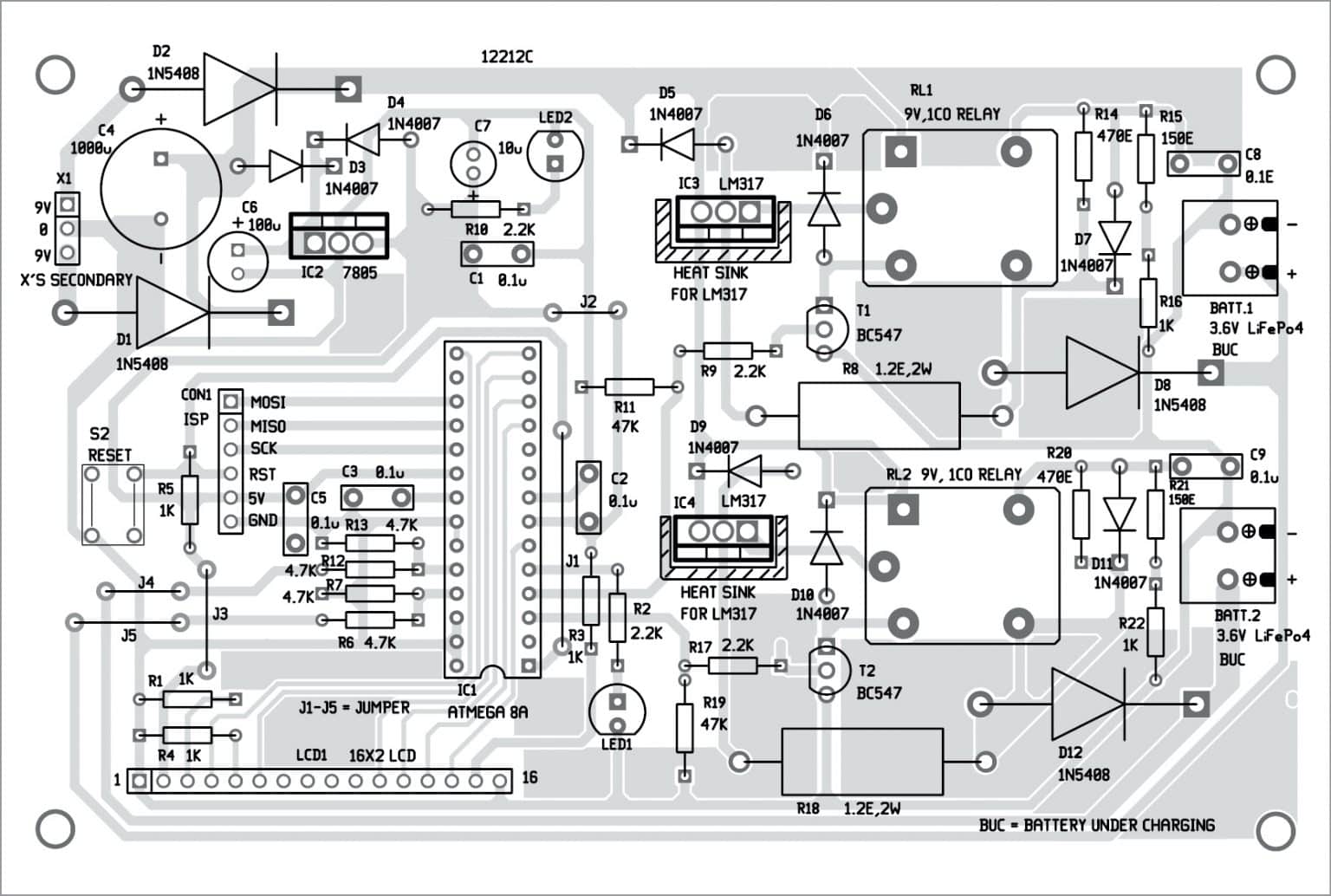
Fig. 1: LiFePO4 1S battery and TP5000 charger module Circuit and working. Circuit diagram of the little LiFePO4 battery charger is shown in Fig. 2. The pnp transistor S8550 (T1) used in the circuit routes input DC supply to the battery through silicon diode 1N4007 (D1). Transistor T1 is controlled through LM358 (IC1) op-amp.

In this video, I will show, how to make a charger for 4S1P 12.8V battery pack with current and voltage control. For maki How to make LiFePO4 battery charger. This application report shows how to modify the bq24650EVM LiIon battery charger to be a LiFePO4 battery charger. The only required changed is to the feedback resistors that set the battery charger regulation voltage. However, only changing the regulation voltage results in the charger beginning to recharge the battery when the battery voltage This circuit is designed to charge a 12V battery at 50mA, but it can be easily scaled up to higher voltages and currents with suitable components. Diodes D1 and D2, and resistor R2 provide a constant voltage of 1.2V at the base of Q1, as the base-emitter voltage will always force 0.6V.
12V LiFePO4 Battery Charger Made From A 15V/25A Low Cost ... Circuit Diagram
The LiFePO4 battery charger circuit (Figure 1) is designed around an Op-amp LM358, a PNP transistor S8550, a diode (1N4007), and a few other passive components like resistor, capacitor, etc. Op-Amp LM358 is used here because it is known for having large dc voltage gain, large out and ut voltage logic swing (VLS), and has a wide range of power LiFePO4 cell may be charged by CN3058E or MCP73123, if you want to make the charger yourself, condensers and heat-sink is necessary. It may also charged using a 3.6V power source and a resistor. LiFePO4 6V/12V/24V battery pack can just use a lead acid charger unless it's out-of-balance.