Making a SelfPowered Generator Circuit Diagram This is a simple function generator that works in the audio frequency range. It can be useful for amplifier testing, experimentation in DSP. LOGIN Author's prototype for Arduino based frequency generator. Circuit diagram of the sine, square and ramp Arduino-based frequency generator is shown in Fig. 2. It is built around an Ardunio Uno

In today's video we learn how to make a frequency / tone generator out of simple parts that can be easily obtained, this is a great project for a starter to
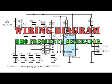
1 Hz to 1 MHz Frequency Reference Generator Circuit Circuit Diagram
1) Using IC 4049. Using only one low-cost CMOS IC 4049 and a handful of separate modules, it is easy to create a robust function generator that will provide a range of three waveforms around and beyond the audio spectrum.. The purpose of the article was to create a basic, cost-effective, open source frequency generator that is easy to construct and used by all hobbyists and lab professionals. How to Calibrate. The 50 Hz being generated from pin 1. Hobbyists possessing a frequency meter can easily calibrate this crystal controlled time base generator circuit by merely hooking up the meter to pin 7 of IC1 (Q4) and fine-tuning C2 until a display of 204.800 Hz is seen on the meter.
The 9 simple sine wave generator circuits presented in the following article are easy to build, since they incorporate a small number of ordinary electronic. It is possible to make the output frequency of the sine wave adjustable by replacing the R1 and R2 with fixed resistors and by putting a potentiometer in series, and it is certainly

10 Useful Function Generator Circuit Diagrams Explained
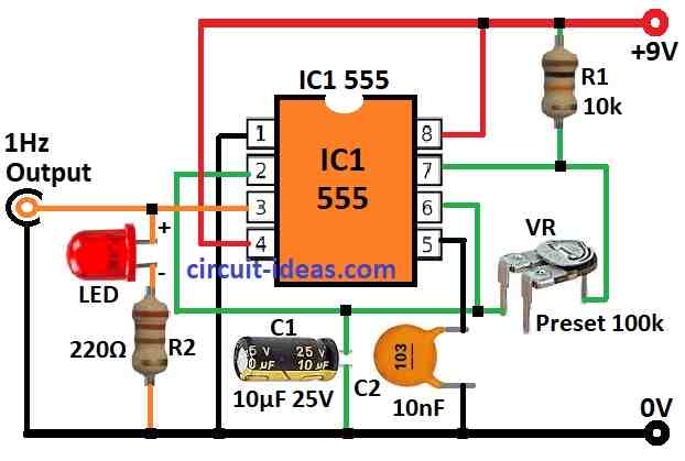
In my last instructable i showed you how to build pwm signal generator, and i used it to filter some other waveforms from it. In this instructable i will show you how to make simple function/frequency generator, how to drive relay with it and how blink led without arduino. All you need is: 10uF cap ; 1uF cap ; 100nF cap ; 2 x 10nF cap ; 100 pF This circuit is built around the waveform function generator IC 8038 capable of generating frequencies up to 300 KHz. My circuit is designed to generate signals up to 100 Kilo-hertz.Lets learn how to build a crude signal generator with variable frequency, amplitude and duty cycle. This circuit is built around the waveform function generator IC The bridge circuit is C1 R4a and C3 R4b. R4 is a dual-ganged potentiometer and controls the frequency, which is 1/2πRC. Assuming R4 is central, say 2k, this would be 1/(2*π* 5k * 0.01u) = 3kHz. The lamp is a small 12V incandescent light bulb.As the filament heats up, its resistance goes up, reducing the current through it, reducing the gain and amplitude at the output, so you have a very
