Mastering Arduino Circuit Diagram Circuitio.io helps you create and prototype electronic circuits with Arduino. You can drag and drop components, get a Bill of Materials, a wiring guide and test code for your project. KiCad EDA Arduino Wiring Diagram Maker. KiCad is a cross-platform and open-source electronics design automation suite for PCB and circuit diagram design. This tool can create accurate PCB layouts using a suite of components and even has a 3D viewer tool so that you can inspect the PCBs that you design. Of course, it also has a schematic drawing

Learn the fundamentals of Arduino hardware, software, and programming. Find out how to create circuits, use sensors and actuators, and communicate with electronic signals. Learn how to build electronic projects and prototypes with Arduino, a popular open-source development board. Find free Arduino projects with neatly illustrated circuit diagrams, detailed explanations, and relevant code for each project. Learn how to design and simulate Arduino circuits using online tools and platforms. Find out the features, benefits, and examples of Arduino circuit diagram maker tools.

Arduino Circuit Diagram Maker Online
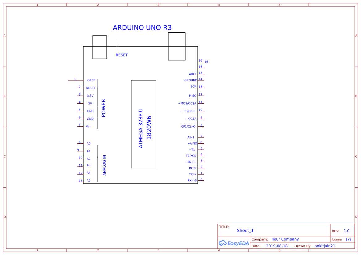
Learn how to analyze the basic Arduino schematic diagram using the Arduino UNO board as an example. See the power supply, microcontroller, USB bridge and input/output sections and their functions. Learn how to use schematic diagram maker tools like Fritzing and EasyEDA to design and simulate your Arduino circuits. Find out the key components, symbols, and benefits of schematic diagrams for Arduino projects.
Learn how to create circuit diagrams for Arduino projects easily online with a user-friendly interface and a library of components. Find out the benefits of using an online circuit diagram maker and the difference between Arduino and other electronics devices. Learn how to create professional-quality circuit diagrams for your Arduino projects using online tools. Compare the features and benefits of Tinkercad, CircuitLab, Fritzing, Autodesk Eagle, and PCBWeb. The example circuit diagram above is a correct way to draw the LED circuit that you should build. As seen in the diagram, the signal (current) from the Arduino will exit from digital pin 12, goes through a 220 Ohm resistor into the anode end of the LED, exits out of the cathode end of the LED, and then back into the ground pin of the Arduino
