Mastering Stability The Ultimate Guide to Gyroscope Stabilizers Circuit Diagram This is a relatively simple, visually effective balancing robot project that only requires four components to make. Detailed video, instructions, schematic, and code at: 40 // supply your own gyro offsets here, scaled for min sensitivity 41 mpu. setXGyroOffset (-479); 42 mpu. setYGyroOffset

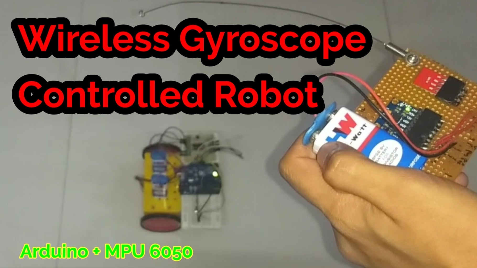
I have attached a video above to show the working of the project. You can see in the video above how the robot moves when the Gyroscope sensor is tilted in that direction. Now enjoy the wireless gyroscope robot. Hope you learned something from this instructable. If yes, then please share it with your friends. Also don't forget to leave a like.
Arduino two weel self Balancing Robot Circuit Diagram
In Step 2, we discussed the importance of reducing lag to maintain gyroscope's accuracy. When modifying the Arduino code, avoid using delay() and Serial.print(). The serial monitor and its printing functions use USART serial communication. Arduino sends data to the serial monitor on the computer via the HC-05 wireless communication. Short answer Arduino gyroscope stabilizer: An Arduino gyroscope stabilizer is a device that uses the data from a gyroscope to stabilize an object. It can be used in various applications, such as drones, robots, and cameras. The device processes the data from the gyroscope and sends corresponding signals to control motors or other actuators to […]

The fundamental principle behind gyroscope robotics lies in gyroscopic stabilization. A gyroscope consists of a spinning disk or wheel mounted on an axis within a frame. This ingenious technology relies on the use of gyroscope sensors to provide essential stability and orientation control in robotic systems. Understanding the key components It is best to position it at the center of the robot, between the two wheels. The sensor will be responsible for detecting the robot's tilt and providing feedback to the Arduino. Step 4: Connect the Gyro Sensor Connect the gyro sensor to the Arduino board using jumper wires. Typically, the MPU6050 has four pins: VCC, GND, SDA, and SCL.

Gyroscope Robotics: Revolutionizing the Future of Automation Circuit Diagram
Arduino Uno you can also use Arduio nano too, but some changes in connections and codes need to be made. Piece of cardboard,I will be using 27cm*8cm rectangular piece. Dual shaft Gear Motor some call it as BO Motor and L298N Motor driver. Gyroscope + Accelerometer module I am using MPU-6050. Hot glue , Jumper wires and other small supporting