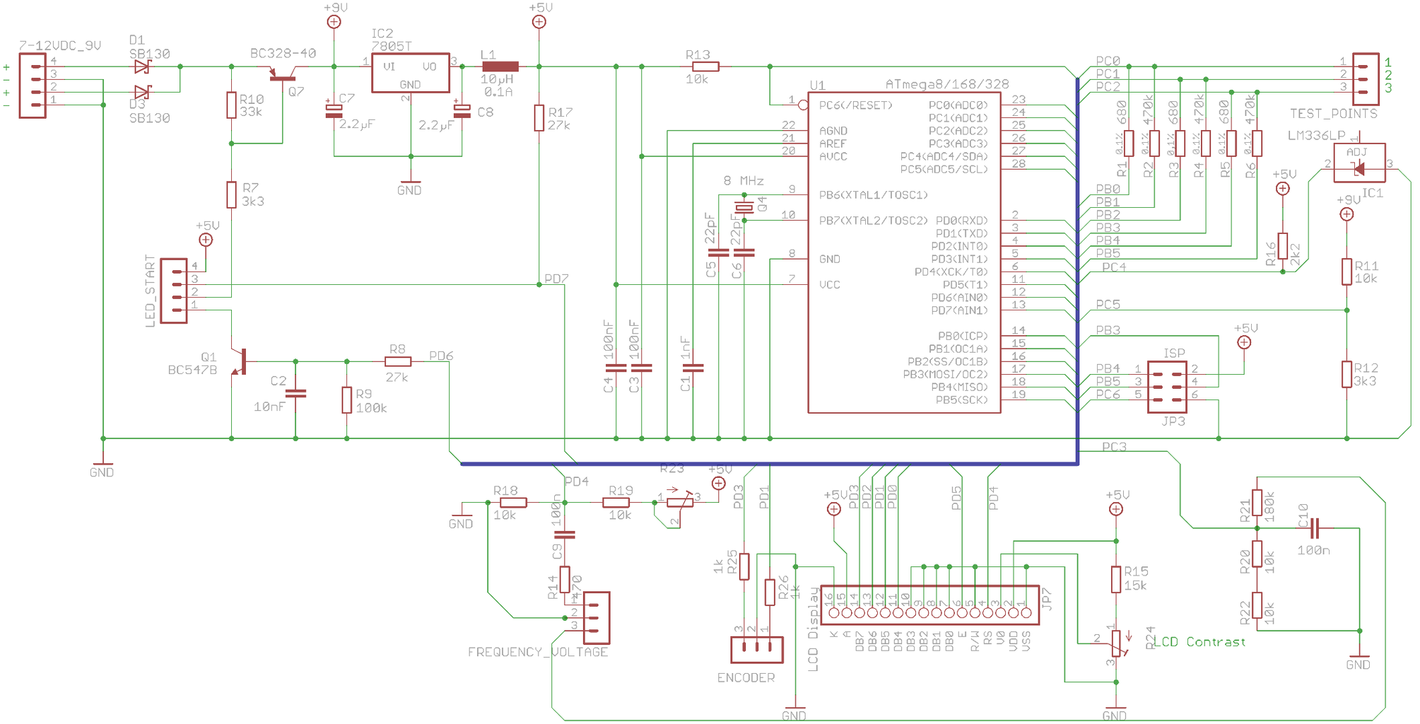
PCB Testing Circuit Diagram Functional testing mimics the final electrical conditions of the PCB and checks the operation of the entire PCB as well as the different components. This often is the last testing in the manufacturing process to confirm whether the PCBs work or not in the given electronics products.
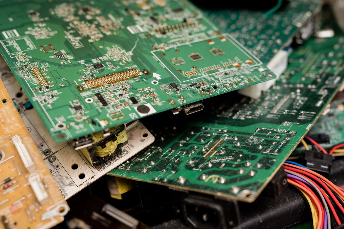
Printed Circuit Board, or PCB, lays the foundation of modern electronic industry. As a combination of various electronic components, it consists of a variety of electronic components, including resistors, diodes, capacitors, transistors, and fuses. Almost all consumer devices, from microwaves to washing machines, use PCBs. However, functional testing is required when the final products are Testing PCBs involves using various methods and tools to ensure that all the individual elements of a PCB perform optimally, making up a high-quality PCB assembly. This article delves into the methods, procedures, and requirements of PCB testing.
Step Guide: How to Test a Circuit Board Effectively Circuit Diagram
Ultimate Guide To PCB Testing PCB assembly testing methods are an integral part of the manufacturing process. The testing methods and investigation of each failure are adapted and improved upon regularly. Here we share details on the various classes of electronics and a variety of PCB testing methods. This guide is intended to provide an accurate and informative collection of this information.
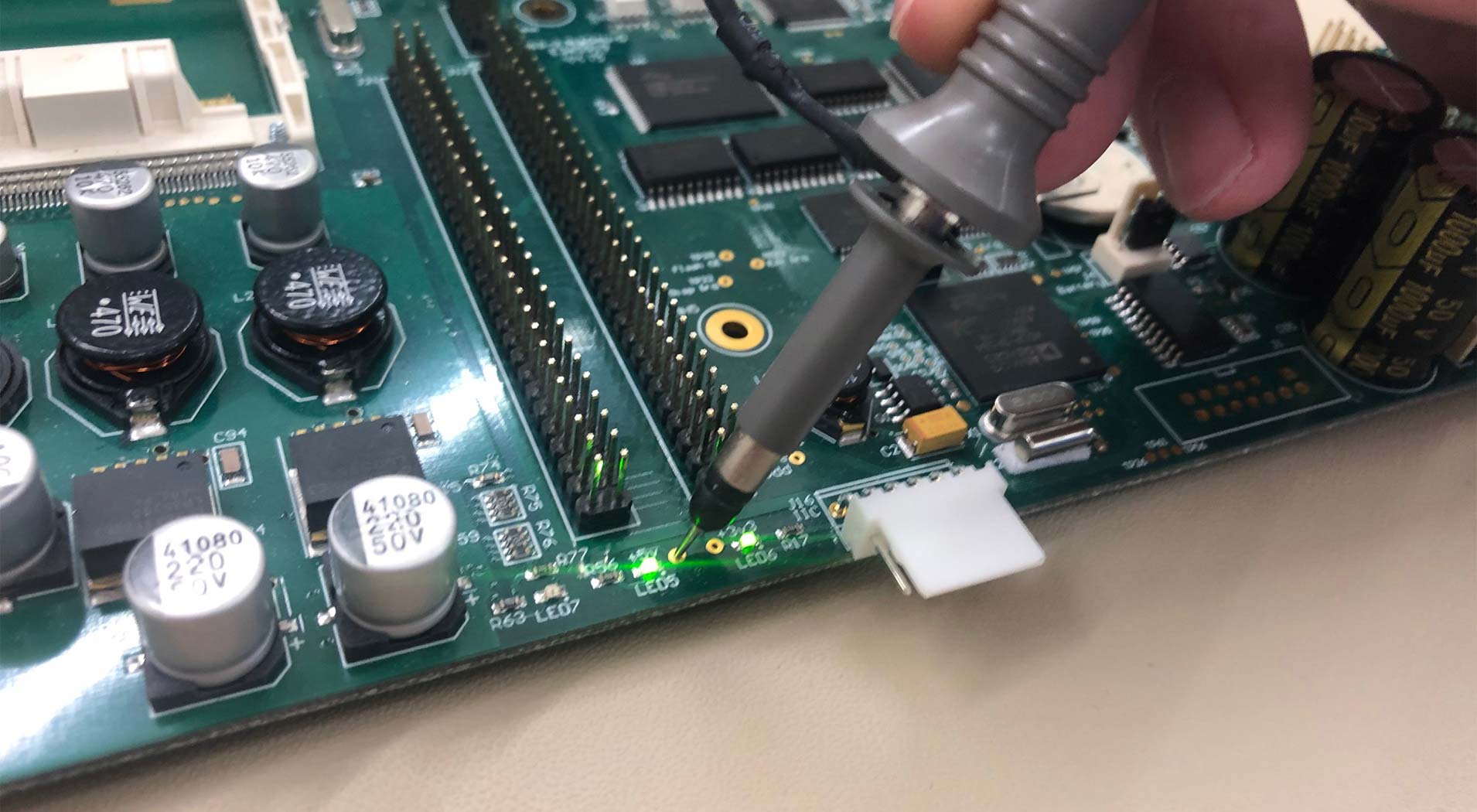
The printed circuit board (PCB) is a crucial component of the electronics sector and helps in various applications. Therefore, it is essential to test the PCBs to ensure the design complies with the specifications and that the final product is of excellent quality. This article will cover the crucial procedures involved in testing a PCB, […] This technique is particularly effective for diagnosing faults in completed circuit elements, offering a valuable tool for modern PCB troubleshooting. Analog Signature Analysis to Test the Unpowered Printed Circuit Boards (PCBs) One of the best essential devices used for detailed analysis of faulty components in a circuit is a Curve Tracer. It ensures the diagnosis of faulty components earlier and paves the way for the effortless functioning of a circuit board. However, you must have special skills and knowledge before testing the electronic components of your PCB. But how to test the electronic components in the safest way?
How to Test Electronic Components On a Circuit Board? Circuit Diagram
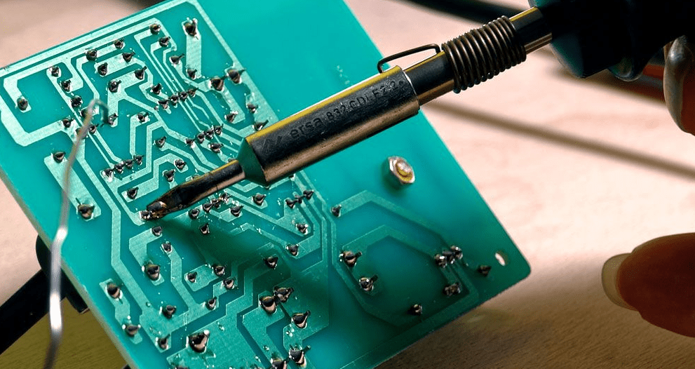
Learn how to test PCB board with our guide to 8 common methods, including visual, functional, thermal, and electrical testing. Learning how to test a circuit board is not as difficult as one would think. Here is a list of instructions and tools to ensure your design is functional. Discover our comprehensive guide on how to test a circuit board effectively. Master the art of troubleshooting circuits with professional techniques.