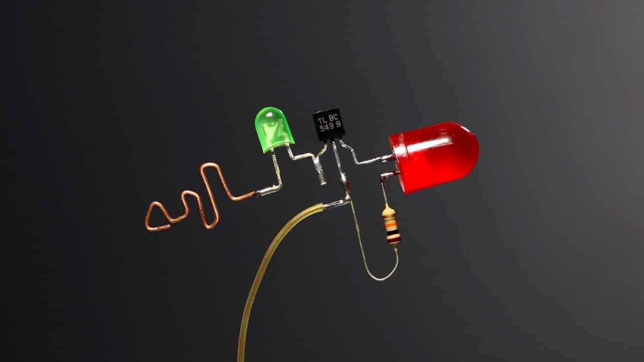
Schematic of the lightsensing circuit Circuit Diagram A light sensor circuit is a simple yet practical project, commonly used in applications like automatic night lights or brightness-sensitive devices. In this guide, we'll create a circuit where an LED lights up in the dark using a PNP transistor. How It Works.

Variable resistor VR 1 is used to adjust the sensitivity of LDR i.e., on what intensity of light, the circuit triggers the load (LED). Another input voltage is taken from the voltage divider network using resistor R1 and R2 which forms a voltage divider network that divides Vcc into two parts thus ½ Vcc volt is available at inverting input. It detects the quantity of light present in the environment and the results can be detected by the brightness of the LED. This circuit may be useful for knowing the working of LDR (Light Dependent Resistor) or Photoresistor, the working of NPN Transistor, and the impact of the sensitivity of the resistor on the circuit.

Light Detector with Sensitivity Control Circuit Circuit Diagram
Light Detector Sensor Circuit Diagram: The circuit of light detector is very simple and easy to build with very few components. As you can see in the LDR circuit diagram, it can be a distinguished as two smaller circuits; a) Voltage divider made using LDR (LDR1) and a Potentiometer (RV1) b) Output (LED D1) in our switching circuit made using a
This circuit can be used to automatically control and turn on-off lights or any loads depending on the brightness of ambient light, by adding a relay at the output. The sensitivity a.k.a the brightness at which the circuit switches on the load can also be controlled by using a potentiometer.
Light Detector Sensor: Building a Simple Circuit Circuit Diagram
The 330K Ohm Resistor and LED can be replaced with virtually anything to trigger a signal or an event. For example, a 9 Volts Relay would be used to make an absence-of-light activated switch. To make this circuit operate in reverse (the LED turns on when there is light), simply just exchange the positions of the Variable Resistor and the LDR.

Step 11: Connect the Power Supply and the Circuit is Now Ready! How This Circuit Works. First things first: The resistance of LDR (Light Dependant Resistor) is inversely proportional to the intensity of light falling on it. It implies that if the intensity of incident light is high, the resistance of LDR will be less and vice versa.