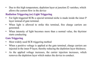
SCR Circuit Diagram The below figure shows the application of an SCR as a switch to ON and OFF the power supplied to the load. The AC power supplied to the load is controlled by applying alternate triggering pulses to the SCR. The resistors R1 and R2 protect the diodes D1 and D2 respectively. The resistor R limits the gate current flow.
An SCR (silicon controlled rectifier, or thyristor) is a semiconductor switching device, with two power terminals, called the anode (A) and cathode (K) and one control terminal called the gate (G). If terminal K is taken positive with respect to A, the SCR is reverse biased and will block current from flowing. Zero voltage switching controls proportionally turn on and off each full cycle of the power line. By varying the number of AC power line cycles, the SCR provides power to the heaters. With a variable time base, the optimum number of cycles turned on/off is achieved. This method produces less RFI line noise than phase angle fired SCRs.

State Relays): The Switching Device Circuit Diagram
contactor, an SCR provides fast response and high resolution as well as the ability to limit current and regulate load voltage, current or power. Disadvantages to using an SCR Power Control can include low power factor, high harmonic currents and radio frequency interference (RFI) when using phase-fired power controllers.
425 AMP THREE-PHASE SCR CONTROLLER 1.0 INTRODUCTION TO SCR POWER CONTROL Since the development of SCR power controllers in the late 1950™s, the power handling capabilities of SCR™s (silicon controlled rectifiers) have advanced from a few hundred watts to many megawatts. So, too, the use of SCR power controllers in industrial applications has However, it is possible to use the TRIAC as a driver for another switching device, as shown in Figure 11. This scheme allows a low-power SSR to control high-current loads by means of external, high-power SCRs. Figure 11 shows how we can use a TRIAC along with three resistors to produce the two controlling signals of Figure 9(B). The above figure shows the use of SCR to switch ON or OFF a.c. power to a load R L.Resistances R 1 and R 2 are for the protection of diodes D 1 and D2 respectively.Resistance R 3 is the gate current limiting resistor.To start the circuit, switch is closed.During the positive half-cycle of a.c. supply, end A is positive and end B is negative
SCR Principles And Circuits Circuit Diagram
One useful application of the SCR is in DC-powered 'alarm' circuits that use self-interrupting loads such as bells or buzzers; these loads comprise a solenoid and a series switch, and give an action in which the solenoid first shoots forward via the closed switch, and in doing so, forces the switch to open, thus making the solenoid fall back and re-close the switch, thus restarting the action

This method can be effectively used in applications requiring RMS current control or load power control. Battery Charger using SCR. Fence chargers primarily require a high voltage generator stage, where a high switching device like an SCR becomes highly imperative. SCRs thus become specifically suitable for such applications where they are
