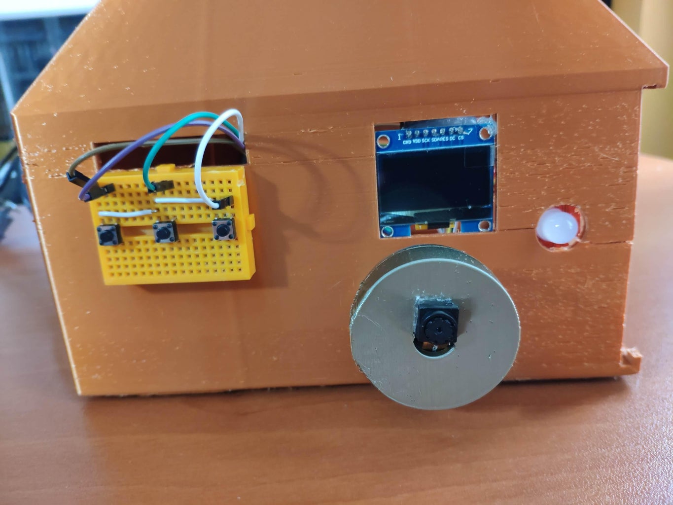
time indoor air quality monitoring using the Circuit Diagram azure-iot-device psutil pyserial . azure-iot-device is for the edge sdk libraries, and pyserial is for reading serial port. The imports look like this: import time, sys, json # from influxdb import InfluxDBClient import serial import psutil from datetime import datetime from azure.iot.device import IoTHubModuleClient, Message . Quite self

With the advancement of technology, it is now possible to create affordable, real-time air quality monitoring systems that can be easily implemented in homes, offices, and public spaces. Project Goals. This project aims to develop a real-time air quality monitoring system using the ESP32 microcontroller and the Blynk IoT platform.

Based Air Quality Monitoring and AQI Measurement System Circuit Diagram
Previously we have also built an IoT based Air pollution monitoring system using ESP8266, The collected data is displayed in real-time on an OLED screen using the Adafruit libraries. By continuously monitoring these parameters, the system offers a snapshot of air quality conditions, enabling users to assess and respond to changes in their In this tutorial, we will walk through the process of building a real-time air pollution monitoring system using Java and the Internet of Things (IoT). We'll leverage sensors to collect air quality data, process that data with Java, and display it through a web interface. Air pollution is a critical environmental issue that affects health and An IoT-powered system for real-time air quality monitoring and analysis. This project integrates environmental sensors with a machine learning model to predict and assess air quality indices. Features include data visualization, predictive analytics, and automated alerts for actionable insights.

Testing and calibrating the sensor. The initial step involves calibrating the sensor. To achieve this, connect the sensor to the circuit and allow it to remain powered on for 24 hours to complete MQ135 Air Quality Sensor. The MQ-135 gas sensor senses the gases like ammonia nitrogen, oxygen, alcohols, aromatic compounds, sulfide and smoke.The MQ-3 gas sensor has a lower conductivity to clean the air as a gas sensing material. In the atmosphere, we can find polluting gases, but the conductivity of the gas sensor increases as the concentration of polluting gas increases.
IoT based Air Pollution Monitoring System using Arduino Circuit Diagram
By carefully selecting and integrating these components, you can create a robust and reliable real-time air quality monitoring device. This device will enable you to measure and analyze air quality data, providing valuable insights into the environment and helping to take informed actions to protect health and well-being. The necessity for real-time monitoring of Air Quality is very glaring. So in this project, we are going to build an ESP32 Air Quality Monitoring System using Nova PM SDS011 sensor, MQ-7 sensor, and DHT11 sensor. We will also be using an OLED Display module to display Air Quality Values.
