Wind Turbine Design Formulation Circuit Diagram It has been written specifically for implementing the 1kW version of a wind turbine design from Hugh Piggott. The turbine is described in detail in his 'How to build a wind turbine: the axial flux windmill plans' guide, available from (which in turn could lead to a short circuit), overheating of equipment and, as

Understanding the circuit diagram of a wind turbine is essential for anyone who wants to make the most of their wind turbine system. Knowing how the components are connected and how they interact with each other can help you troubleshoot problems, optimize your system for maximum efficiency, and ensure that the turbine is generating electricity

Understanding the Basic Circuit Diagram of a Simple Wind Turbine
Overall, a simple wind turbine circuit diagram is a vital tool for understanding the electrical system of a wind turbine and how it functions. It provides a visual representation of the various components and their interconnections, helping engineers and technicians troubleshoot any issues that may arise. The design of wind turbine blades The blades on the turbine catch the wind, and the rotor spins. This spin turns a generator, which produces electricity that you can use to power your home. Here is the simple design proposed, such as a small wind turbine for home use or low-power usage. It requires a low initial cost and gives the best return, in terms of electrical energy.
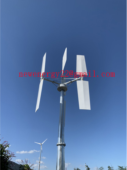
Instead of winding a vertical axis wind generator yourself, a simpler idea would be to configure the VAWT mechanism with a high watt generator or a dynamo through a correctly calculated gear or pulley/belt ratio.. For example, the above shown 10 kv dynamo has a specifications of generating 10000 watt at around 3600 RPM, which implies that if the a pulley ratio of 1:100 is configured, the Wind turbine schematic diagrams provide a visual representation of how wind turbines work and how their various components interact. This can be highly beneficial for engineers, technicians, and anyone involved in the design, installation, operation, or maintenance of wind turbine systems.

Wind Turbine Circuit Diagram
The rectifier circuit is typically integrated within the wind turbine's power converter, which consists of several stages such as the rectifier stage, DC-DC converter stage, and inverter stage. The rectifier stage: At the heart of the power converter, the rectifier stage converts the AC output from the generator into pulsating DC. Using LTC1042 IC. The latest IC LTC1042, a 12V DC permanent magnet motor, as well as a low-cost power FET may be used to build a basic wind-powered battery charger.The voltage output is equivalent to the RPM of the DC motor, which is utilized as a generator. The LTC1042 controls the voltage output and complete the following necessary tasks: